Horizontal loaded polygonal wall
Determination of load capacity for a polygonal, horizontal loaded wall. The shape shall be concave (e.g triangular or five-angular shape). Openings (window and doors) can be inserted.
The supporting conditions along the edges can be:
- free
- simple
- restrained
The wall is only supported along the edges
Method of calculation
The determination of the load capacity is according to the yield line theory.
The load capacity is found through iteration.
Flexural strength fxk1
The characteristic flexural strength having a horizontal plane of failure.
The value is transferred automatically from the headings. The value can, of course, be overwritten in the current calculation.
Flexural strength fxk2
The characteristic flexural strength having a vertical plane of failure.
"Storey high walls of light weight concrete" (AAC) is often adjoined with glue giving a flexural strength fxk2 normally not higher than 0,5 MPa.
The value is transferred automatically from the headings. The value can, of course, be overwritten in the current calculation.
Horizontal load
This load is practically always wind load, either directly acting on the exposed wall or through the evenly distributed wall-ties. The value is always positive.
Thickness
Rules in the N.A. for minimum thickness of walls shall be applied
No reduction is necessary for joint depths less than, or equal to, 3 mm. In cases of joint depths exceeding 3 mm, the thickness is reduced by the full joint depth.
Example:
If the masonry is constructed using units (150 mm) with a one-sided recessed joint, with a depth of 10 mm, the thickness will be: 150 mm - 10 mm = 140 mm.
Type of wall
The yield line theory is valid for masonry and "storey high walls of light weight concrete". The safety factors can be different though
"Storey high walls of light weight concrete" (AAC) is often adjoined with glue giving a flexural strength fxk2 normally not higher than 0,5 MPa.
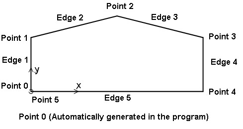
Define an edge
The shape shall be convex, i.e. a triangel, quadrangle, five-, ... or a ten-angle.
The shape is defined through a table with the coordinates and the supporting conditions.

Figure 1. Definition of a polygonal wall
The first coordinate are defining the line from (0,0).
NOTE!: Do not write (0,0) as the first coordinate, since this point automatically is the starting point (point 0).
The last coordinate should go to the starting point (0,0).
The supporting conditions along the edges can be:
- free
- simple
- restrained
Define an opening
Openings are defined through a table giving the shape, placement and dimensions.
Following shapes are possible:
- Quadrangle
- Diamonds
- Ellipse
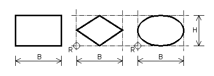
For all 3 types the placement of the opening are defined by the coordinates X og Y (The horizontal and vertical distance from the lower left corner of the wall to the point of reference R for the opening).
The point of reference for an quadrangle opening is the lower left corner of the opening.
The point of reference for a diamond or an ellipse shape opening is the lower left corner of the circumscribed square (see figure)
The dimensions of the opening are the width B and the height H. For a diamond or an ellipse shape opening the width and the height is of the circumscribed square.

Figure 2. Openings
Openings can be combined by overlapping constructing more complicated figures if necessary.