Masonry beams
The program designs masonry beams, following the design rules in Eurocode 6: Design of masonry structures - Part 1-1: General rules for reinforced and unreinforced masonry, EN 1996-1-1.
The design rules are verified by recent and former tests conducted on masonry beams. The correlation between the design model and the results from the experiments is appropriate, when realistic material parameters are used. The test material consists of more than 100 masonry beams with varying parameters.
The effective beam length is the clear span + Minimum(the bearing length, or the effective height).
In the calculation, the shear load is determined at a distance of ½ * (the effective depth) from the face of the support. This causes the shear load to be slightly less than the reaction.
The initial shear strength (fvk0) may be increased if the ratio of the shear span to the effective depth is less than 2. That is:
av/d < 2.
fvk0 may be increased by a factor:
2d/av ≤ 4
If fvk0 is increased the shear load shall however be calculated at the face of the support. This implies for asymmetrical loads that the shear capacity can be different on the right and left side.
Furthermore, a criteria for the bearing capacity concerning strain in the tension area in the middle(length) of the beam has been introduced. The tensile strain in the lower bed joint must be below 0.5 ‰ for the bearing capacity to be assumed adequate. Tests made at the Danish Institute of Technology, Masonry have shown this value to be safe for beams in normal practice.
Reinforcement in the top produce a fixed-end moment:
The fixed-end moment is not calculated to be greater than half the actual positive moment (when the beam is considered to be simply supported) even when the bearing capacity of the moment at the ends are greater.
Naturally, it is necessary to ascertain that the contruction adjacent to the beam is capable of resisting the moment that is transferred from the fixed-end.
Initial shear strength (fvk0)
The initial shear strength is the part of the shear strength not resulting from friction. The initial shear strength (fvk0) is occasionally called the cohesion.
The value is transferred automatically from the heading "Masonry".
The value can, of course, be overwritten in the current calculation.
Diameter of reinforcement (bottom)
The most common diameter for embedded reinforcement in a prefabricated lintel is:
5 mm, when prestressed
8 mm, when not prestressed, but other diameters can be used
The most common diameter for bed joint reinforcement systems is 3 - 5 mm.
If the lintel is wider than the masonry in the integrated beam (see figure) there will be a tendency of deflection perpendicular to the plane of the beam. The displacement and the asymmetrical reinforcement will furthermore reduce the load capacity.
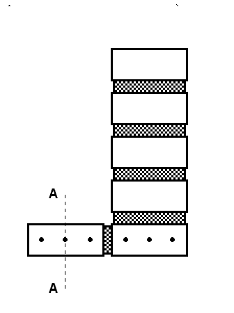
Figure 1. L-shaped beam
Thus the number of reinforcement should only include half the reinforment outside the contour of the beam. E.g. line A - A in the figure
Diameter of reinforcement (top)
The most common diameter for bed joint reinforcement is 3 - 5 mm.
Characteristic modulus of elasticity Ek
The value is transferred automatically from the module "Masonry".
The value can, of course, be overwritten in the current calculation.
Point loads
The design values of the point loads. Any number of point loads can be given
Compressive strength, fk
The value is transferred automatically from the heading "Masonry".
The value can, of course, be overwritten in the current calculation.
Prestressed
Prestressed or non-prestressed reinforcement.
The prestressed reinforcement gives a greater stiffness, and thus a smaller
vertical movement of the beam.
The design bearing capacity of the masonry beam is equivalent for prestressed and
non-prestressed lintels.
Reinforcement
Reinforcement steel for lintels must meet the requirements of (EN 10080/10088), and must be ribbed/profiled.
Reinforcement steel for lintels in the outer leaf and walls around wet rooms must be corrosion resistant, for example austenitic stainless steel, meeting the requirements of EN 845-2 and EN 845-3.
Reinforcement steel for lintels in the inner leaf and walls between dry rooms can be unprotected carbon steel.
The characterisic yield strength, or the 0.2%-stress: For tentor steel or comb steel the value is respectively 550/450 MPa. For corrosion resistant steel, the values differ, ask the supplier.
The characteristic modulus of elasticity for reinforcement steel can under normal circumstances be set to 200000 MPa.
Height
The height includes the lintel itself.
It is important the courses included in the height, are effectively
joined throughout the length of the beam.
The height of the beam typically measures from the bottom of the lintel to
the damp proof course.
Using a (TB - gutter) will not reduce the height of the beam, but the initial shear strength should be reduced: The reduction shall correspond the estimated reduction in thichness (10 mm). I.e. a factor (t - 10 mm)/t, where t is the thicness of the masonry beam.
Reinforcement (top)
The moment bearing capacity can be increased by placing upper reinforcement in the left and/or the right side of the beam.
Distance to the centroid of the reinforcement (bottom)
The vertical hight from upper limit of the clearing (bottom of the lintel) to the centroid of the reinforcement. If the reinforcement is equally placed in two layers the centroid is in the middle between the two layers.
The effective depth (d) is determined by the program as the total depth (=height) of the beam minus the distance to the centroid of the reinforcement minus 20 mm. The 20 mm takes into consideration:
1. that the upper bed joint by the damp-proof course can not contribute to the height of the beam
2. placement tolerances (e.g. prestressed reinforcement often causes the lintel to arch during the embedment mortar's setting).
Distance to the centroid of the reinforcement (top)
The distance from the upper limit of the beam to the reinforcement is typically the height of one course.
Width of clear opening
The design value of the width of the clear opening below the masonry beam.
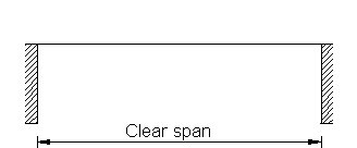
Figure 2. Clear span
Is often equal to the design width of the opening, but in cases where there are recessed joints with a joint depth of more than 3 mm, the clear span should be increased by the joint depth on both sides.
It is recommended to control the dimensions of the beam and the placement of possible point loads for crude errors by using the function "Drawing".
Thickness
Rules in the N.A. for minimum thickness of walls shall be applied
No reduction is necessary for joint depths less than, or equal to, 3 mm. In cases of joint depths exceeding 3 mm, the thickness should be reduced by the full joint depth.
Example:
If the masonry is constructed using a unit with a thicness of 150 mm with a one-sided recessed joint, with a depth of 10 mm, the thickness shall be: 150 mm - 10 mm = 140 mm.
Number of reinforcement bars (bottom)
The most common amount of reinforcement bars in prefabricated lintels, are 2 - 4 wires
When using bed joint reinforcement, the spacing between reinforcement bars must be two times the diameter. The minimum depth of mortar cover, from the reinforcing steel to the face of the masonry, is 15 mm for autistic stainless steel.
Number of reinforcement bars (top)
Reinforcement systems most commonly have 2 bars.
When using bed joint reinforcement, the spacing between the reinforcement bars must be two times the diameter. The minimum depth of mortar cover from the reinforcing steel to the face of the masonry is 15 mm for autistic stainless steel.
Uniform load
The design value of the beam's uniform load can result from the dead load of the masonry in and above the beam, and from dead load and live load on storey partitions.
Height of loading:The "hidden arc" determine the uniform load on the masonry beam. The "hidden arc" divert the load from the the masonry beam.
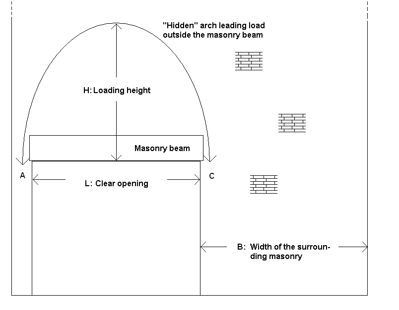
Figure 3. Illustration of loading height
For situation I and II
The masonry beam are subjected to a parabolic load. For this type of load it is quite difficult to estimate the section forces and a uniform load with the equivalent peak height is therefore assumed
- Situation INarrow column near a corner, expansion joint or similar:
In case the masonry at one (or both) side(s) is narrow and thus only a small resistance for horizontal loads (Area A on the figure above) the height of the loading is set to: H = L.
- Situation II
When the horizontal dimensions of both supports of the masonry are large compared with the clear span the height of the loading is set to: H = L/2 (when B > L for both supports)- Situation III
The masonry are carried by consols around the corner and support A does not exist
In that case there is no "hidden arc" and all masonry above are load on the masonry beam
Bearing length
Example 1:
The masonry beam is constructed using a prefabricated lintel,
which is supported by masonry in the plane of the beam.
The bearing length (u) is set equal to, or less than, the physical bearing length of the lintel.
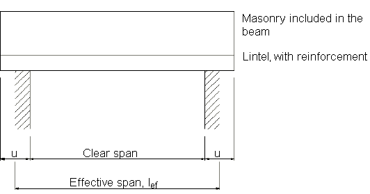
Figure 4. Support. Lintel
Example 2:
The masonry beam is constructed by embedding a prefabricated bed
joint reinforcement in one or more bed joints. The bearing length u is set equal to,
or less than, the actual anchorage length of the reinforcement, but at least 100 mm.
The actual anchorage length should not be less than the one indicated in the report.
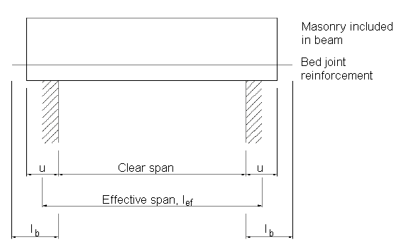
Figure 5. Support. Reinforcement system
The design value of u is to be stated. When using recessed joints with a joint depth of more than 3 mm, u must be reduced by the full joint depth.
It is recommended to control the dimensions of the beam and the placement of possible point loads for crude errors by using the function "Drawing".