Vertical loaded wall (EN 1996 - 1 - 1)
Determination of load capacity for a vertical loaded wall without openings according to EN 1996 - 1 - 1. The wall may have a horizontal load as well.
To determine the load capacity in the uncracked situation (fxk1 > 0) the extended Navier is used.
The load capacity should not be based on the flexural strength in case failure will lead to a progressive collaps though.
If the proportion between E0k og fk is smaller than 500 the calculation is terminated. The model in EN 1996-1-1 is empirical and optimized to E0k/fk = 1000. For low values of this proportion the load capacity is increasing for decreasing values of fk (and all other parameters fixed). This seems wrong and the calculation is terminated. Instead the Ritter formula can be used or fk can be reduced to a level giving E0k /fk > 500. Any reduction of fk is regarded conservative.
Biaxial loading: There are no rules in EC6 concerning biaxial bending of masonry walls. It is suggested that the rules from EC2, chapter 5.8.9, formula (5.39) is used in cases where biaxial load is applied on masonry walls.
Supporting conditions
A wall is always supported at the top and bottom and the number of supports is at least 2. Vertical support at the end of the wall gives the number of support to 3 or 4.
In EN 1996 - 1 - 1 the supporting condition at the top and bottom are characterized through a factor ρ2 equal to the value 0,75 or 1,00. In this module consideration is taken to the supporting conditions through the interval of eccentricities and thus ρ2 is always set to 1,0.
A vertical supporting wall can be regarded as having enough stiffness if the connection between the actual wall and the supporting wall is bonded, secured by wall-ties or in a similar way connected. The length of the supporting wall should be at least 1/5 of the height and the thickness 0.3 of the actual wall to be supported.
Openings are included as shown in the sketch below (from EN 1996 - 1 - 1)
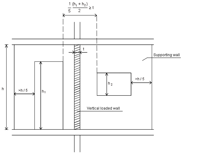
Figure 1. Minimum length of vertical supporting wall
Density
The value is transferred through the heading “Masonry”. The value can be overwritten.
In several modules the dead load of the wall pr square meter is determined as the density multiplied the wall thickness. If any rendering should be added to the dead load, the density should be corrected (e.g set 10 % higher to include the render). The thickness should be exact, thus giving the “exact” load capacity.
Module of elasticity E2 and E0k
E0k is the module of elasticity of the load carrying wall (inner wall)
E2 is the module of elasticity of the outer wall (if any)
If there is no outer leaf E2 is not significant
For small cross-sections (smaller than 0,1 m2) the parameters of strength is reduced according to EN 1996 - 1 - 1.
The value is transferred through the heading “Masonry”. The value can be overwritten.
Interval of eccentricities
In EN 1996 - 1 - 1 annex C a method for determining the vertical eccentricity based on an elastic model is described . This model is very sensitive to the assumptions of the stiffnesses in the adjoining members though.
In this module an alternative approach is choosen. It is examinated if an arch of compression in equilibrium with the actual vertical and horizontal loads can be placed inside the wall and fullfilling the conditions in EN 1996 - 1 - 1 in the top, bottom and in the middle of the wall. See figure 2 below.
The limitations are given by the end-user. The limits are positive to the right and negative to the left. The definition of positive/negative is related to the horizontal load that is positive to the left. (i.e. positive horizontal load and positive eccentricity deflect the wall in the same directions)
In EN 1996 - 1 - 1 annex C a method for determining the vertical eccentricity based on an elastic model is described.
This model is very sensitive to the assumptions of the stiffness's in the adjoining members and is not used in this module. Instead, an alternative approach consistent with EN 1996 – 1 – 1 is chosen:
It is examinated if an arch of compression in equilibrium with the actual vertical and horizontal loads can be placed inside the wall and fullfilling the conditions in EN 1996 - 1 - 1 in the top, bottom and in the middle of the wall. See figure 2 below.
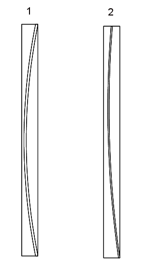
Figure 2. Placements of archs of compression.
In arc 1 the wall is stiffly supported in the full thichness at the top and bottom
In arc 2 the wall is stiffly supported in the full thichness at the bottom and in the top it is supported in the center e.g by a narrow lath of wood
This approach implies that an interval for the eccentricity is to be given (instead of a fixed value). These intervals are given at the top and bottom and called "Interval of eccentricities"
The "Interval of eccentricities" are relevant for both the EC 1996 - 1 - 1 method (cracked) and the extended Navier method (uncracked). The parameter einit is implemented in the "Interval of eccentricities" using following procedure:
- EN 1996 - 1 - 1 - method: The "Interval of eccentricities" are narrowed (reduced) in both sides with einit.
- Extended Navier method: The "Interval of eccentricities" are moved einit unfavorable as a function of the wind load. The "Interval of eccentricities" are, if necessary, reduced to be inside the thickness of the wall. The resultant of the load is assumed placed in the (unfavorable) thirdpoint equvivalent to a triangular distribution of stresses.
In both cases the corrected "Interval of eccentricities" are labelled the "Design interval of eccentricities".
The differens is explained below:
- EN 1996 - 1 - 1 - method apply the plasticity theory assuming the cracked cross-sections redistributing the stresses so the arc of compression is placed in favour in top and bottom regarding the eccentricity in the middle.
- The extended Navier method apply the elasticity theory assuming an uncracked cross-section and conservative reactions in top and bottom. A "moved" "Interval of eccentricities" is thus more conservative than a narrowed.
In the figure below the "Design interval of eccentricities" for the EN 1996 - 1 - 1 method is shown.
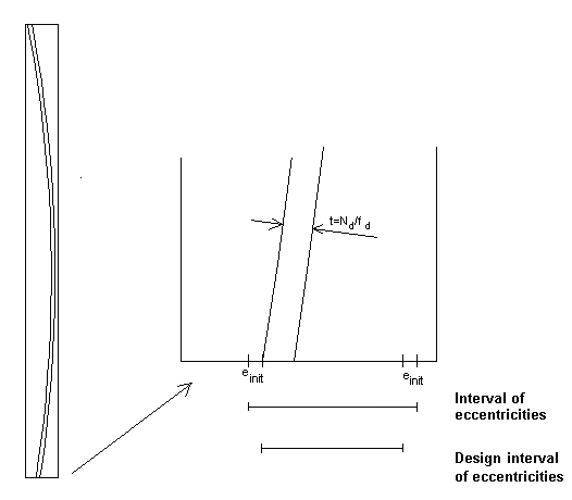
Figure 3. "Narrowing" the "Interval of eccentricities" with einit for the EN 1996 - 1 - 1 method
Using this approach the condition (6.4) in EN 1996 - 1 - 1 is automatically fullfilled at the top and bottom. In the middle-section the eccentricity is the distance from the compression arc to the center of the wall. The eccentricity due to creep ek determined from (6.8) in EN 1996 - 1 - 1 is added. The reduction factor Φm can thus be determined.
Determination of interval of eccentricities
An interval of eccentricities in the top or bottom gives the range for the resulting vertical load
The interval of eccentricities depend on the actual supporting conditions.
A wall supported by a stiff rigid foundation will tend to be subjected to a reaction at the right or left side depending on the horizontal load. See figure 4.
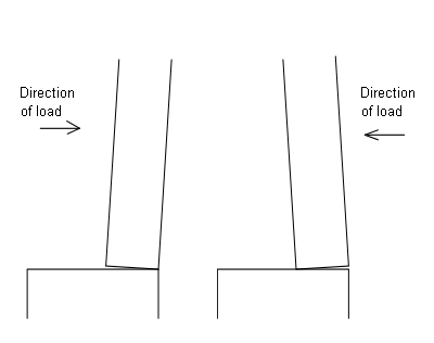
Figure 4. Wall supported by a stiff foundation.
Regardless of the direction of the horizontal load, the reaction on the foundation will move, giving a reaction in favour to the construction.
If the wall is supported by a slack/elastic slab the wall will be supported as shown in figure 5.
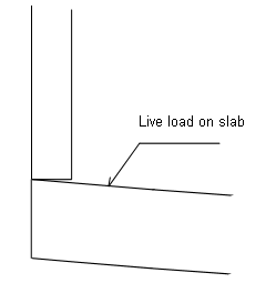
Figure 5. Wall supported of an elastic slab subjected to live load.
If the slab is elastic the interval should be set to half the thickness. Elastic slabs could e.g be wooden frames.
If a wall is subjected to vertical load through a planke as shown in figure 6 the interval of eccentries will be as indicated
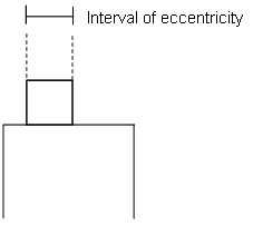
Figur 6. Interval of eccentricity for a wall subjected to vertical load through a plank .
If the cross-section is more similar to a wooden-board (see figure 7), the eccentricity should be reduced. It is proposed to set the interval of eccentricity equal to 3 × h, maximum b, I.e. interval = minimum(b, 3h). Where b is the width of the board and h the height.
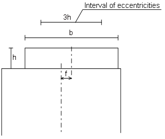
Figur 7. Interval of eccentricities for a wooden board. The interval should be symmetrical to the wooden board.
Examples are illustrated subsequent
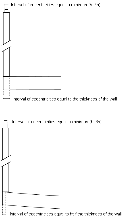
Figure 8. Examples
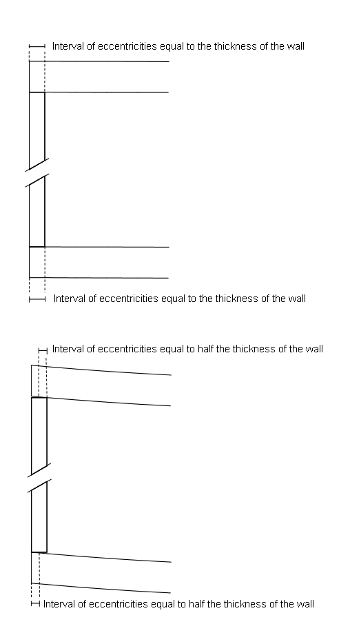
Figure 9. Examples
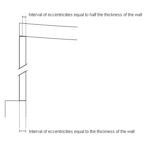
Figure 10. Examples
Compressive strength, fk
The value is transferred automatically from the heading "Masonry". The value can, of course, be overwritten in the current calculation.
For small cross-sections (smaller than 0,1 m2) the parameters of strength are reduced according to EN 1996 - 1 - 1.
Flexural strength fxk1
The characteristic flexural strength of masonry having the plane of failure parallel to the bed joints.
The load capacity should not be based on the flexural strength in case failure will lead to a progressive collaps.
For small cross-sections (smaller than 0,1 m2) the parameters of strength are reduced according to EN 1996 - 1 - 1.
The value is transferred automatically from the heading "Masonry". The value can, of course, be overwritten in the current calculation.
The geometry of the wall
The load capacity is determined for a single-leaf wall or a load-bearing inner leaf in a cavity wall (using the cubic formula).
The wall shall be supported horizontal in the top and bottom. The wall can additional be supported along one or two vertical edges of the wall.
Vertical load
The assumptions for the calculation in this module are a wall supported at the top and bottom and without openings. The load at the top of the wall shall be corrected for openings if any. This shall be done geometrically. E.g for a 6,0 m long wall with 2 openings each with a width of 1,0 m shall the vertical load be increased a factor: 6/(6-4) = 1,5. This correction gives the correct load in the middle height where the failure will occur. The vertical load can normally be extracted from the module “Calculation of loads”
The dead load of the wall shall not be included in the value. The dead load is calculated via the density and thickness
A vertical point load can be distributed in 1:2. The height of the wall is e.g 2,8 m. A point load at the top on the central part of a wall (central part = minimum 2,8 m / 4 = 0,7 m horizontal from a vertical edge) can be regarded as having a horizontal extension in the wall of: 2 x 1,4 m/2 = 1,4 m.
Is the concentrated load direct on the vertical edge the horizontal extension in the wall can be estimated to: 1 x 1,4 m/2 = 0,7 m.
In both situations vertical split-forces shall be thoroughly examined
Horizontal load
This load is practically always wind load, either directly acting on the exposed wall or through the evenly distributed wall-ties. The value is always positive (going to the left). The eccentricity for the vertical load can be positive or negative and thus acting in the same or opposite direction of the wind load.
If the capacity of the outer leaf is used for stiffening the load bearing inner wall the total windload shall be applied on the inner wall
Thickness. Outer leaf
When calculating the ratio of slenderness consideration shall be taken to the total stiffness of the combined wall. The stiffness of one leaf is proportional with t3 x E. Thus the modules of elasticity and thickness shall be stated for both leafs
The thickness should be reduced in case joints are recessed.
Rules in the N.A. for minimum thickness of walls shall be applied