Calculation of loads
Determination of design horizontal and vertical load according to EN 1991
Distance to a shore with a dominating wind
The load will be increased if distance to a shore with a dominating wind is less than 25 km
Distance from outer corner to the vertical edges of the regarded wall
The windload is variating over the roof
If the wall subject to calculation is a part of a facade wall or load bearing innerwall, the program shall "know" the location of the wall in order to determine the contribution to the vertical load from the windload on the roof.
If the wall subject to calculation is a part of a gable wall, the information is relevant in order to determine the average height of the gable on top of the wall regarded in order to determine the contribution to the vertical load.
If the wall subject to calculation is a part of an outer wall, i.e. a facade or gable wall, the location (near a corner) is significant for the horizontal load.
The width and length of the building
The width is the distance between the front-sides of the facade. The length is the distance between the front-sides of the gables
Eaves and verges
Eaves and verges (Overhang of the roof at the facade and gable)
Horizontal distance shall be given.
Density and thickness of inner leaf/partion wall
The values are transferred through the heading "Masonry" or “LW Concrete (EN 12602)”. The value can be overwritten.
Rules in the N.A. for minimum thickness of walls shall be applied
In several modules the dead load of the wall pr square meter are determined as the density multiplied the wall thickness. If any rendering should be added to the dead load, shall the density be corrected (e.g set 10 % higher to include the render). The thickness should be exact thus giving an “exact” load capacity.
Density and thickness of outer leaf/veneer wall
Rules in the N.A. for minimum thickness of walls shall be applied
The values are transferred through the heading "Masonry" or “LW Concrete (12602)”. The value can be overwritten.
In several modules the dead load of the wall pr square meter are determined as the density multiplied the wall thickness. If any rendering should be added to the dead load, shall the density be corrected (e.g set 10 % higher to include the render). The thickness should be exact thus giving the “exact” load capacity.
Dead load. Ceiling
The ceiling is the upper most horizontal structural floor. It is often made by other materials than the remaining slabs.
In some constructions is the ceiling omitted. The values are then set to 0
"The load bearing distance" is the distance perpendicular on the actual wall from where the load is tranferred to the wall
The construction of the ceiling is normally supported by the facades (and a load bearing partition wall, if any)
If the actual wall is a gable wall or a non-load bearing separation wall "The load bearing distance" should be set to nil.
If the actual wall is a facade or a load bearing partition wall "The load bearing distance" can normally be set to half the distance between supports
Characteristic dead load. Roof surface
The dead load of rafter, planks, roof tile, insulation, internal covering, etc. The value is given in kN pr m² of the sloping roof (not horizontal).
If the actual wall is a gable wall or a non-loadbearing partition wall the value is insignificant.
Height and number of storyes. Height of socle
The height of a storey is measured from top slab to top slab.
It is pressumed that the construction is an integer number of normal storeys with the same height and load. Over every storey is a "normal" slab. Over the upper storey is the ceiling.
The height of the socle is the vertical distance from terrain to the slab of the lower floor.
Eccentricity of the vertical load
The eccentricity of the vertical load from the "normal" slabs.
The eccentricity is positiv towards the the center of the building.
Eccentricity of the vertical load from the ceiling
The eccentricity of the vertical load from the ceiling.
The eccentricity is positiv towards the the center of the building.
Eccentricity. Load from the roof construction
The eccentricity is positiv towards the the center of the building.
Dead load, live load and the "Load bearing distance" for normal slab
The "Normal" slab (I.e. all slabs except the ceiling) is pressumed subjected to the same dead- and live load.
"The load bearing distance" is the distance perpendicular on the actual wall from where the load is tranferred to the wall
"The load bearing distance" can normally be set to half the distance to the adjacent supports
Live load. Ceiling
The ceiling is the upper slab and normally different loaded than "normal" slabs.
In some constructions the ceiling is omitted. The values are then set to 0
"The load bearing distance" is the distance perpendicular on the actual wall from where the load is tranferred to the wall
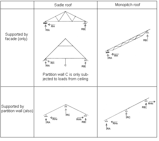
Type of roof
Following options are available:
- Supported by facade (only) or supported by partion wall (also)
- Sadle roof or monopitch roof
For a monopitch roof combined with a facade there is a choice between the lower and higher facade.
A roof "Supported by partion wall (also)" is a wall supported by the facades and a partion wall in the middle
A sadle roof is pressumed symmetrical. See figure below

Figure 1. Type of roof
Roof angle
The angle between the roof surface and horizontal (in degrees).
Category of terrain
The 5 categories to choose between are:
- 0 Sea: Sea or coastal area exposed to the open sea
- I Lake/flat area: Lakes or flat and horizontal area with negligible vegetation and without obstacles
- II Open land/Near fields: Area with low vegetation such as grass and isolated obstacles (trees, buildings) with seperation of at least 20 obstacles heights
- III Urban/industrial area/permanent forest: Area with regular cover of vegetation or buildings or with isolated obstacles with separation of maximum 20 obstacles heights (such as villages, suburban terrain, permanent forest)
- IV City area: Area in which at least 15% of the surface is covered with buildings and their average height exceeds 15 m
Local directional factors can (if relevant) reduce the wind load.
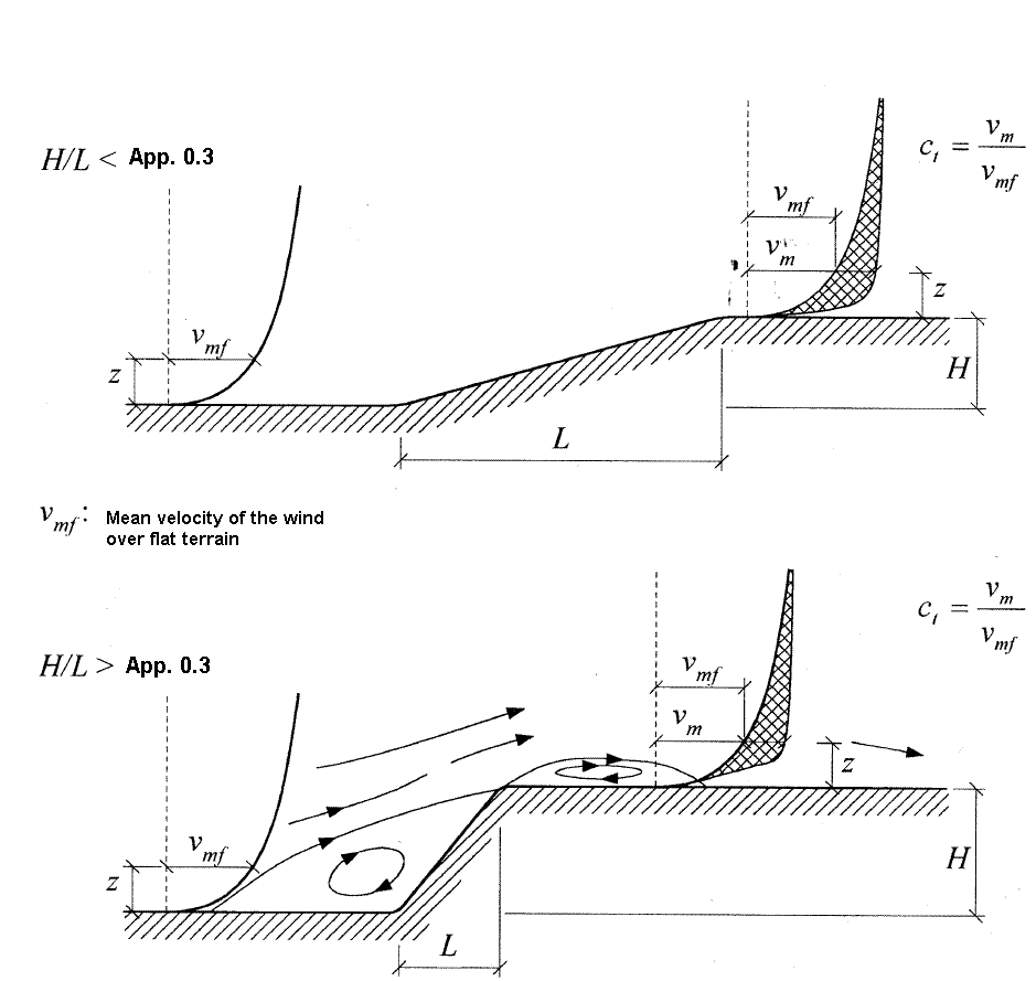
Factor of orography
Non-horizontal terrain can be taking into consideration using this factor
The factor is: Min(1+2H/L; 1.6) for H/L > 0.05. See figure below for definition of H and L

Figure 2. Orography
Categories of use
The categories of use span from A - E and determine the relevant value for ψ0 according to EN 1990
The definitions of categories is given in EN 1991 - 1 - 1
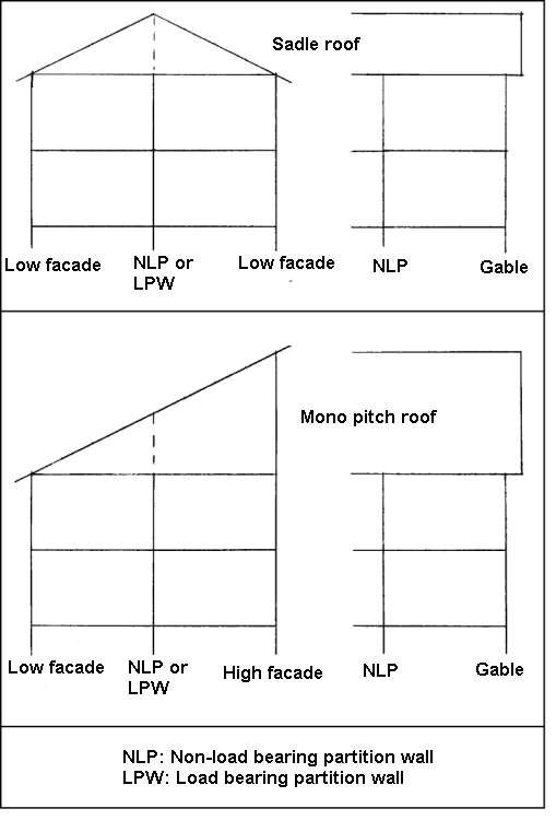
Type of wall
Actual types of walls in the calculation:
- Facade wall: Outer wall parallel to the ridge of the roof
- Gable wall: Outer wall perpendicular to the ridge of the roof
- Load bearing partition wall: Load bearing partion wall parallel to the ridge of the roof.
- Non load bearing partition wall: A wall not receiving loads from the roofs.

Figure 3. Type of wall